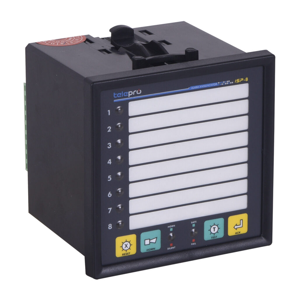
ISP-8 ALARM ANNUNCIATOR

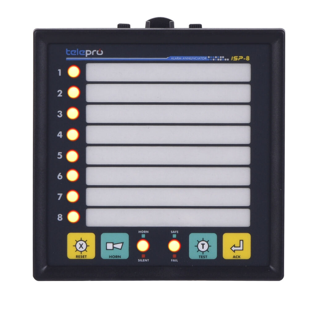
  • 8 Channels Led Technology
  • Communication And Event Recording Options
  • Reliable Performance Under Electromagnetic Interference
  • Working With Different Voltage Levels. (24/48,110/220 Vdc)
  • Easy Programming With ISPsimtm software
  • Capability Of Relay Output Selection For Each Channel By Using Push-Buttons On The Front Panel
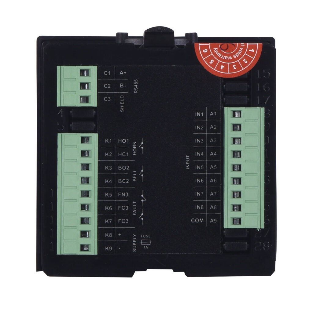
  • Isolated RS485 Port And Modbus RTU Protocol Support
  • High-Quality And Long Life  Power Supply  With Protection For Over Temperature, Shortcircuit, Overcurrent/Overvoltage, 

TELEPRO-ISP-8 Alarm Annunciator is a flexible, functional and reliable product used in the protection and control automation systems.

Our product, combining low cost with good quality, compact and unique design, is an unrivaled product with optional communication and optional event recording features.

Each of 8pcs channels is isolated.They are protected by opto-coupler, harmonic suppressors and noise filtering software. The device can be safely used under the environment containing high electromagnetic noise which is continuously met.

Horn and bell selection can be done with push-buttons as well as all the parameters can be set via ISPsimTM software (just for one having communication option).

Our models having optional event recording provide event recording with 1 msec resolution.

Response and release times for the environment with electromagnetic noise are to be programmed between 3-250msec (for the ones having communication options)

Optional RS485 communication port supports Modbus RTU and could be easily integrated with the SCADA systems.
ISP-8 could be easily labeled by the aid of dedicated labeling template provided by TELEPRO®.

PHOTO GALLERY

GENERAL FEATURES

MODULAR CONSTRUCTION

TELEPRO-ISP8 Alarm Annunciator is an advanced technology product providing compact, flexible programming and labeling options.
It could be easily used in the wide area protection systems, thanks to the parallel working feature.

RELAY OUTPUTS

TELEPRO-ISP8 provides 2pcs of NO FormA type dry contact relay outputs by default. Outputs are set to HORN or BELL
alternatives.All channels can be set to one of these alternatives with software or push-buttons on the front panel. Additionally, it provides FAULT relay having FormC type NC/NO with the common terminal so as to indicate internal system faults.

COMMUNICATION (Optıonal)

Our models with communication and event recording; provide galvanic isolation protection as a standard, support Modbus RTU protocol through integrated RS485 port and get easily connected with the SCADA systems.

PROGRAMMABLE RESPONSE AND RELEASE TIME

There are “software programmable” response/release times which provide flexible and safe performance for protection against induced magnetic fields resulted from maneuvers i.e CB opening/closing especially. With the help of ISPsimTM software; Response and release time are independently set between 3msec and 250msec. Response time is set to 5msec, release time is set to 20msec by default.

INTERNAL EVENT RECORDER (Optional)

It is an ideal device for sequential event recording in 1ms resolution timestamps and software supported reporting features for wide area protection systems. All the event records in the annunciators working in parallel with 1-1920 channels quantity can be instantly monitored from one station via the internet connection with IP based.
"Integrated event recording system supported with HEIM-48 and HEEP-3000-RTU designed by TELEPRO® are recommended to be used for wide area protection systems requiring high performance."

HIGH-QUALITY POWER SUPPLY

TELEPRO-ISP8 can be supplied with 2 different voltage level in order to meet the different alternatives used in the distribution system automation. It can be freely connected to the voltage levels of 24/48V, 110/220V DC . Power supply with the design of protection against shortcircuit, overcurrent/overvoltage and over temperature, guarantees long life.

LED INDICATION

LED indication, providing ultra bright illumination which could be seen even in the high lighting environments, is supplied as default for all models.

DISPLAY AND LABELING

Having front panel design which membrane featured, providing high-quality appearance. Easily changed, printed out labeling system with the front label size of 7x63 mm dedicated for each channel, is having a user-friendly design . The window for each channel can be named with label template supplied by TELEPRO® . Whenever requested, labels can be easily changed.

FULL SOFTWARE CONFIGURATION

With the help of ISPsim™ software (*); relay selection (horn-bell), response and release time as well as the ModbusID setting can be programmed.
ISA18.1 Sequence Code is set to Code M (Manuel RESET) as standard.
In addition, horn-bell selection of all channels can be safely (and independently from software) set with the push-buttons on the front panels without opening panel doors. With the advantages resulted from the unique design, needs for dip switches are eliminated.

CASE AND MOUNTING

TELEPRO-ISP8, is provided in case configuration, with panel type and UL94V0Self-extinguishstandard. Mechanical protection of our standard case is of IP51. Having Standard dimensions of (96x96x75 mm) and weight of 300gr. With user-friendly screwed mounting system, it can be fast and safely mounted / dismantled.

INPUTS

All inputs are isolated with opto-coupler, protected with varistor, having common return terminal and filtered. Fulfill EU Electromagnetic Compatibility (EMC) and Low voltage directive (LVD). False alarm possibility is completely eliminated. The maximum input current is 5mA, the input voltage can be ordered as 24/48V, 110V/220V DC upon request.

EASY TO USE

8 pcs of dry contacts from the field are to be connected to inputs of ISP8.
Each channel can be set to HORN or BELL relay according to operator choice. These settings provide a difference in LED indication too. The corresponding channel turns to GREEN when setting to BELL, it turns to RED when setting to HORN. (Optionally Red/Yellow alternative available)
Wiring connection and other details are provided in the Installation Manual supplied with the device.